Posts

Showing posts from September, 2015

Industrial Safety Systems

Image
The Industrial Safety Systems and Their Types Industrial automation has minimized the human interaction with the machines but has not completely eliminated it. Industrial safety systems are introduced to protect the human who work in hazardous plants. Some examples of these are oil and gas, chemical and nuclear plants. The industrial safety systems not only protect the humans but also protect the environment and the plant itself from the chemical reactions. These systems do not control any process but in fact come into play when it is not possible to control a process through normal means. They are rather installed as a protective measure and are quickly becoming the need of every working environment. There are various types of safety systems in place and their use depends on the type of industry they are used in. Here is a look at some of them. Process Control Systems (PCS) They are installed for the monitoring of the manufacturing environment and they control the manufact
CoDeSys - industrial IEC 61131-3 PLC programming

Image
CoDeSys  is the acronym of Controller Development System. It is a development program which enables the user to create visualizations of the operations and processes of the applications. CoDeSys contains an integrated visualization system which is unique and very useful. Its applications of programiming controllers are built according to the International indsutrial standadrs. CodeSys software is easy to install and is freely available from the company’s site. This software enables the operator to draw a visual chart of the controller’s data and can watch and assess the performance easily. No additional tools are required for this software. A manual comes with the software which contains all the information and it has integrated visual program. The credit of developing CoDeSys goes to the software company located in Germany and its most recent version was released by the company in 1994. Five programming languages are used in CoDeSys which enable the programming of differen

PROFIBUS

Image
 PROFIBUS PROFIBUS or Process Field Bus was introduced in 1989 and it is sometimes confused with PROFINET. It links plant automation modules with the process control. PROFIBUS uses a multi drop single cable to connect the devices. This method is cost effective especially for larger sites when compared to old methods. Its installation cost is low and it is easy to find faults as well because it is a single cable. Types of PROFIBUS There are two types or versions of PROFIBUS commonly known as 1.    PROFIBUS DP 2.    PROFIBUS PA Here is a brief introduction to both of these types. PROFIBUS DP It runs over two core screened cable that is violet sheathed and its speed varies from 9.6Kbps to 12Mbps. A particular speed can be chosen for a network to give enough time for communication with all the devices present in the network. If systems change slowly then lower communication speed is suitable and if the systems change quickly then effective communication will happen through

Analog Input/Output Modules

Image
Analog Input/Output Modules Analog Input Modules To select an analog input module the consider the followings: *Voltage level. *Current input. *Conversion speed. There are two basic types of A/D converter. The first will perform a conversion every 20 ms (the period of the a.c. mains voltage), which gives a good clean reading free from worries of line frequency interference. The second will convert in 2-20 us, giving the possibility of measuring transient data. *At very high rates the PLC may only have time to act as a data logger, storing the data as it is read, and analyzing it some time after the event to report on or display it. Analog Output Modules *The conversion speed of an analog output is generally <100 us and rarely a problem. * Once the resolution of the module is selected we have only to consider the following points: Voltage level. Load resistance. Typically the minimum load resistance is 300 Ohm. Current output. It is often a

PLC Installation & Commissioning

Image
PLC Installation & Commissioning PLC Installation, Commissioning and Recommendations Typical installation Typical installation (enclosure, disconnect device, fused isolation transformer, master control relay, terminal blocks and wiring ducts, suppression devices). Spacing controllers – follow the recommended minimum spacing to allow the convection cooling. Preventing excessive heat (0–60?) C Grounding guidelines. Power considerations. Safety considerations. Preventive maintenance considerations. Commissioning and testing of a PLC system Checking that all cable connections between the PLC and the plant are complete, safe, and to the required specification and meeting local standards. Checking that all the incoming power supply matches the voltage setting for which the PLC is set. Checking that all protective devices are set to their appropriate trip settings. Checking that emergency stop button work. Checking that all input/output devices a

An application on Conveyor system

Image
Conveyor system This simple application is for a conveyor (moving material machine) and how we implement it using ladder diagram and instruction list. System requirements: 1 . A plc is used to start and stop the motors of a segmented conveyor belt, this allows only belt sections carrying a copper plate to move. 2 . The system have three segmented conveyor belts, each segment runs by a motor. 3 . A proximity switch located at the end of each segment to detect the position of the plate. 4 . The first conveyor segment  is always on. 5 . The second conveyor segment turns on when the proximity switch in the first segment detects the plate. 6 . when the proximity switch at the second conveyor detects the plate, the third segment conveyor turns ON. 7 . the second conveyor is stopped, when the plate is out of detection range of the second proximity switch, after 20 seconds. 8 . the third conveyor is stopped after 20 seconds, when the proximity swtch located at the se

PLC Programming Examples

Image
Programming Examples  Example 1: Write a program (instruction list) to put the number (4000) in a memory location, and the number (41) in another location. divide the first one by the second and put the result in a memory location. solution:    Example 2 : Make a program to increase the counter by one with each pulse from the pulse generator SM0.4 (on rising edge) , and decrease another counter by the same pulse. Solution:  steps of solution would be like this:  1 . put zero in memory location vw100.   2 . put (10) in the memory location vw110.   3 . with each rising edge from SM0.4 (every 30 sec), we increase memory location vw100 by one. and at the same time decrease  vw110  by one. the program will continue like that without any instruction to stop. #please note that:  MOVW => move word  INCW => increment word  DECW => decrement word Example 3: Put a value in memory location vw200, and using shift

PLC Instructions

Image
PLC Instructions Functions and Instructions   Relay-type (Basic) instructions : I, O, OSR, SET, RES, T, C   Data Handling Instructions:  Data move Instructions: MOV, COP, FLL, TOD, FRD, DEG, RAD (degrees to radian).  Comparison instructions: EQU (equal), NEQ (not equal), GEQ (greater than or equal), GRT (greater    than).  Mathematical instructions.  Continuous Control Instructions ( PID instructions ).   Program flow control instructions : MCR (master control reset), JMP, LBL, JSR, SBR, RET, SUS, REF   Specific instructions :  BSL, BSR (bit shift left/right), SQO (sequencer output), SQC (sequencer compare), SQL (sequencer  load).   High speed counter instructions : HSC, HSL, RES, HSE   Communication instructions : MSQ, SVC   ASCII instructions : ABL, ACB, ACI, ACL, CAN Internal Relays Auxiliary relays, markers, flags, coils, bit storage. Used to hold data, and behave like relays, being able to be switched on or off and switch other devices on or off. They do

PLC Programming

Image
PLC Programming Programming Languages A program loaded into PLC systems in machine code, a sequence of binary code numbers to represent the program instructions. Assembly language based on the use of mnemonics can be used, and a computer program called an assembler is used to translate the mnemonics into machine code. High level Languages (C, BASIC, etc.) can be used. Programming Devices PLC can be reprogrammed through an appropriate programming device: Programming Console PC Hand Programmer Introduction to Ladder Logic Ladder logic uses graphic symbols similar to relay schematic circuit diagrams. Ladder diagram consists of two vertical lines representing the power rails. Circuits are connected as horizontal lines between these two verticals. Ladder diagram features Power flows from left to right. Output on right side can not be connected directly with left side. Contact can not be placed on the right of output. Each rung contains one output at least. Each output

PLC selection criteria

Image
PLC selection criteria PLC selection criteria consists of: * System (task) requirements. * Application requirements. * What input/output capacity is required? * What type of inputs/outputs are required? * What size of memory is required? * What speed is required of the CPU? * Electrical requirements. * Speed of operation. * Communication requirements. * Software. * Operator interface. * Physical environments. System requirements * The starting point in determining any solution must be to understand what is to be achieved. * The program design starts with breaking down the task into a number of simple understandable elements, each of which can be easily described. Application requirements * Input and output device requirements. After determining the operation of the system, the next step is to determine what input and output devices the system requires. * List the function required and identify a specific type of device. * The need for special operations

Sinking Sourcing I/O

Image
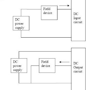
Sinking Sourcing I/O “Sinking” and “Sourcing” terms are very important in connecting a PLC correctly with external environment. These terms are applied only for DC modules. The most brief definition of these two concepts would be: SINKING = Common GND line (-) SOURCING = Common VCC line (+) Most commonly used DC module options in PLCs are: *Sinking input and *Sourcing output module Sinking I/O circuits on the I/O modules receive (sink) current from sourcing field devices. Sinking output modules used for interfacing with electronic equipment. Sourcing I/O: Sourcing output modules used for interfacing with solenoids. PLC AC I/O circuits accommodate either sinking or sourcing field devices. Solid-state DC I/O circuits require that they used in a specific sinking or sourcing circuit depending on the internal circuitry. PLC contact (relay) output circuits AC or DC accommodate either sinking or sourcing field devices.

Programmable Automation Controller (PAC)

Image
Programmable Automation Controller (PAC) Programmable Automation Controller or PAC is an easy to configure PLC style device. It has advanced capabilities and they are already built into its design. It can perform complex functions like loop control, latching, and data acquisition and delivery. They have other advantages too as open architectures are used in their manufacturing and they can connect to almost any device or business system present today. Characteristics of a PAC The term PAC was given by ARC and there were two reasons behind it. To help the users of automated hardware define the applications they need. Give the vendors a term to effectively communicate the characteristics and abilities of their product. ARC also made and explained a few rules or guidelines for a device to be considered as a programmable automation controller. Operate using a single platform : It should be true for single or multiple domains and in drives, motions and process controls.

Remote Terminal Unit

Image
Remote Terminal Unit A  remote terminal unit  ( RTU ) is a  microprocessor -controlled electronic device that interfaces objects in the physical world to a  distributed control system  or  SCADA  (supervisory control and data acquisition) system by transmitting  telemetry  data to a master system, and by using messages from the master supervisory system to control connected objects. [1]  Another term that may be used for RTU is  remote telecontrol unit . Architecture An RTU monitors the field digital and analog parameters and transmits data to the Central Monitoring Station. It contains setup software to connect data input streams to data output streams, define communication protocols, and troubleshoot installation problems. An RTU may consist of one complex circuit card consisting of various sections needed to do a custom fitted function or may consist of many circuit cards including CPU or processing with communications interface(s), and one or more of the following:

Typical Calibration Procedure of Differential Pressure Transmitter

Image
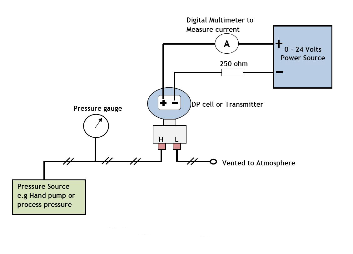
 Calibration Procedure of Differential Pressure Transmitter Set up the differential pressure transmitter, HART communicator, power supply, hand pump, and the multimeter as below (see below calibration setup file). Make sure the equalizing valve manifold is closed. Apply a pressure to the transmitter equal to a lower range pressure (usually it correspond to 4 mA in the transmitter output). For example we have 0 to 100 mBar calibrated range, then the lower range pressure is 0, or let’s say we have -2 psig to 5 psig then we have lower range pressure equal to -2 psig. Read the pressure in the transmitter LCD (or in the HART communicator). Adjust (if any) through the HART communicator so that the output of the transmitter (on LCD) is the same with the applied pressure. Read the mA output of the transmitter by using a multimeter. Adjust (if any) through the HART communicator so that the output of the transmitter (on multimeter) is 4 mA. Apply a pressure to the transmitter equa

Wireless Field Instrumentation

Image
Large-scale, reliable, next-generation plant-wide field wireless system A new architecture for our “Grow” concept Yokogawa launched the world’s first wireless field products conforming to the ISA100.11a standard in 2010 and has led the business ever since. Now, Yokogawa has released a new, large-scale, reliable, next-generation plant-wide field wireless system. In developing this system, which forms the core of field digital solutions, Yokogawa has focused on the following three key features. 1. Reliability: reliable high-performance field wireless and redundant technologies 2. Flexibility: flexible architecture that supports the full range, from small to large-scale plants 3. Openness: open ISA100.11a standard that allows third-party field wireless devices to be connected This new system has been developed in line with Yokogawa’s “Grow” concept of helping customers to grow and enabling ourselves to evolve and continue to offer timely solutions.  →The individual spec